Non-Seismic Methods for Investigating the Interior of the Earth

Geologists and geophysicists have a wide variety of methods for looking into the Earth.

1) Drilling Holes (wells)

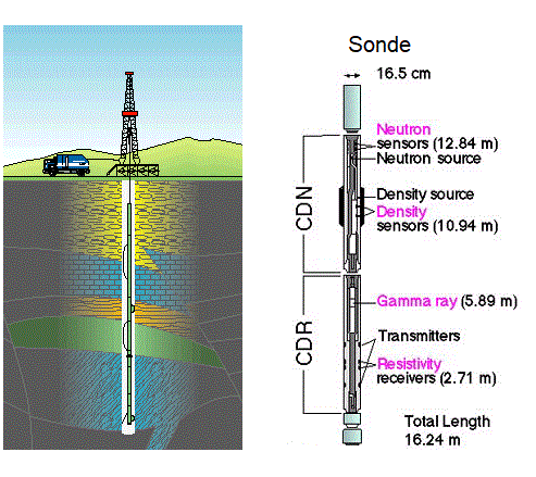
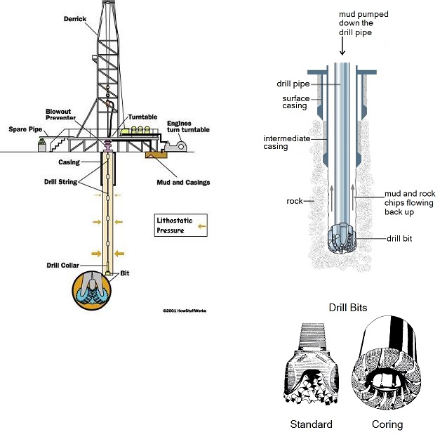
Typical configuration of an on-land oil well drilling derrick.

This is the simplest method in theory, but it is limited in its practical application because of problems with pressure, weight, time, and cost. Drilling rigs can be as small as a device mounted on the back of a truck and as large as stationary rigs tens of metres high and capable of drilling many kilometres into the earth. In the case of a large oil drilling rig (see diagram to the right), a long, hollow pipe with a drill bit on the end is rotated and pushed into the earth. The pipe is hollow so that a liquid mud can be pumped down the inside of the pipe to lubricate the drill bit and carry up debris created by the drill bit as it chews up the rock as it flows back up the outside of the pipe. The density of this mud is carefully controlled so that its weight counteracts the pressure of any fluids trapped in the rocks below and prevents them from explosively shooting out of the drill hole. A heavy valve called a blowout preventer can close off the flow of material up the well if pressure underground overcomes the drilling mud. The well is lined with concrete (called casing) near the surface early in the process for extra reinforcement and to keep loose soil from falling down into the well. For a more detailed description, check out this Kansas Geological Survey primer. Wikipedia has a good description of different drilling methods, too.

The drill pipe (also called the "string") is made up of 10 metre sections that are screwed together. The drill bit is at the bottom of this string. The top-most pipe, called the drive pipe or Kelly pipe, has a polygonal cross-section so that a matching collar attached to the derrick motor can turn it more effectively. More pipes are screwed onto the top of the string as the drill bit goes deeper. As each pipe is added, the Kelly at the top must be unscrewed from the pipe below it, the new pipe added, then the Kelly pipe screwed back on to the top of the new pipe. Wells can be as much as several kilometres long (they are not necessarily vertical), so hundreds of 10 m pipes must be used. Eventually, the weight of all of these pipes becomes too heavy to turn and so heavy that they will break under their own weight. Very deep wells often use more expensive drill bits that are turned by a turbine which is powered by the flow of the drilling mud down the inside of the pipe string so that the pipe itself does not need to rotate.

The drill bits get dull pretty fast, depending on the type of rock being drilled through. As they become less effective, they must be changed. This involves pulling out all of the pipes in the string and stacking them up until the last one is brought up with the drill bit. Small derricks must do this one pipe at a time, while larger (taller) derricks can pull out pipes in twos, threes, or fours. No matter which, it is a long, tedious process to pull up a pipe string then lower it back down again.

This youtube video shows the process of adding a new pipe to the top of the stack. The pipe string is hauled up until the base of the Kelly pipe is exposed. The pipe string is wedged in place so it does not fall back into the hole. The Kelly pipe is unscrewed from the pipe below using two large pipe wrenches. The Kelly pipe is then screwed into another pipe that is waiting in a recessed hole to one side. This is then lifted up and screwed into the pipe that is wedged in at the top of the string (using the same two wrenches). Then the wedge is removed and the pipe string is lowered back into place so the Kelly drive can start rotating the pipe string again. After this, one of the derrick crew can be seen preparing the next pipe to be added to the string.


Lithostatic Pressure
If you have ever gone down to the bottom of a deep pool or done any SCUBA diving, you will know that the deeper you go, the more the water pressure increases and pushes in on your ears. The same problem exists for holes drilled into the Earth. Rocks exert lithostatic pressure in the same way that water exerts hydrostatic pressure or the atmosphere exerts atmospheric pressure.  If the hole gets too deep, the lithostatic pressure collapses the hole. The rock temperature also can pose practical problems for the drilling process as it progresses deeper into the earth.

Kola Superdeep Borehole
The most extreme example of a deep drill hole is the Kola Superdeep Borehole which was made on the Kola Peninsula in northeastern Russia near the Swedish border. Operations began in the early 1970s and ended in the late 1980s, with several gaps for analysis and technical problems. The project was intended to go down 15 km, still well within the crust, but pressure and high temperature (180 oC) halted operations at just over 12 km. The borehole has since been sealed off and abandoned (see below).  


The cap for the Kola Superdeep Borehole: bolted and welded in place.

Analysis
One can get a lot of information out of a 25 cm wide hole in the ground.
a) A geologist is always on site during drilling operations. Their primary job is to analyse the rock fragments as they are brought to the surface and filtered out of the drilling mud. From these, a fairly good picture of the rock formations through which the drill bit is moving can be gained. The geologist needs to be quick in their analysis as new fragments arrive in a steady stream.

b) Once the hole has been drilled out, any of a number of devices can be lowered the hole to take measurements from the rock formations through which the hole passes. The generic term for such a device is a "sonde." They are lowered down on a wire that transmits data back to the surface. Of particular interest are such properties as density, speed of sound, porosity, the type of fluids in the pore spaces, and temperature. The means by which the sonde makes these measurements is described in detail in this Wiki article on well logging

Temperature profiles are obtained by filling the well with water and waiting a few weeks for thermal equilibrium to be reached. A digital thermometer is then lowered slowly down the well to obtain a profile of temperature vs depth. This is useful for understanding the rate of thermal energy flow out of the earth. This knowledge is used to study the local plate tectonic environment, the behaviour of the mantle below the site, and the history of climate change in the region.

c) If a more detailed look at the rocks is needed, a special bit called a "coring bit," can cut out a drill core: a complete cylinder of rock for analysis (see below). This is an expensive process because the drill bit is slower and the drill string must be pulled up several times to install the special bit and to retrieve each section of core. After we have learned something about sedimentary rocks we can come back to these images and see what we can identify.


Cost
On land, a modestly deep drill hole, only a few kilometres, deep can cost over $10 million to make. This is huge amount of money gives you a view of an 25 cm wide bit of the earth. Drilling or coring wells offshore (in the ocean) usually costs about 20 times more than operations carried on land. If a core sample is needed, the cost of that is on the order of $3000 per metre (more if only a short section is needed. Coring the whole well would about double the cost of the well, so on short sections of critical depths are cored. Well logging is much cheaper at a few dollars per metre.


2) Geophysical Imaging:Gravity and Magnetic Surveys
Sensors to detect subtle variations in the Earth’s gravitational or magnetic fields can be towed from aircraft and ships. The maps made from the data collected from these devices allow inferences to be made as to the structure and composition of bodies of rock deep within the crust and upper-most mantle. Gravity differences reflect the presence of rock masses of different density such as high density ore bodies and low-density roots extending into the mantle below mountains. Certain minerals produce their own magnetic field. Both measurements can be used to detect different geologic structure that are deep within the crust and upper mantle where they are otherwise out of sight.

Magnetically susceptible minerals align to the earth's magnetic field as rocks cool from a magma or lava. Since the Earth's magnetic changes episodically, the magnetic field generated by the minerals in the rock can be used to infer when a particular body of rock was formed.

Measurements of variations in earth's gravity field also can be obtained from special satellites. These bob up and down in their orbits as the gravity field weakens or strengthens under them. This effect can be observed from companion satellites or from ground tracking stations.


Aircraft fitted out for a magnetic survey in Ghana.


Magnetic anomaly map of the state of Alaska. Different colours represent differences in the strength of the local magnetic field.


This is a computerized gravity anomaly map of the Chicxulub impact crater just north of Mexico's Yucatan Peninsula. The crater is on the order of 200 km in diameter. It is thought to have resulted from the asteroid impact at the end of the Cretaceous Period which precipitated the extinction of the dinosaurs. Changes to rock density from the impact event preserve a record of the now-eroded-away crater. The crater was discovered using gravity data obtained from a small aircraft.

This shows the process by which basalt rock records the earth's magnetic field orientation as it solidifies between tectonic plates which are moving apart from each other. This was important evidence in the development of the theory of plate tectonics.


3) Ground Penetrating Radar

Ground penetrating radar (GPR) also can be used to detect features below the earth's surface. GPR can be deployed from transmitters towed over the ground on from aircraft and spacecraft. GPR images were used to discover ancient river channels buried under the desert sands in Sudan.

To the left is a comparison of two images in northern Sudan taken from the same orbital flyover of the space shuttle. On top is an image made using visual light showing desert sand. Below is the same image with a superimposed GPR path which clearly shows ancient river channels under the sand.


4) Electrical Geophysical Imaging
Electrical Resistivity Tomography
In this procedure, electrodes are placed in the earth some distance apart (they can be placed in boreholes, when these are present). A current is passed between them and the variations in the electrical potential field between them are mapped. This electrical field is influenced by variations in resistance within the rocks. Different rock types are known to have different electrical resistances, so a lot of information about the distribution of rock types at depth can be inferred from this procedure.

Electromagnetic Induction
Electromagnetic fields also can be used to detect certain types of rock deep below the surface of the earth. An electric current is switched on and off in a large loop of wire (called the transmitter) which is on or just above the ground surface. The electromagnetic field generated by this wire loop produces electric currents within a smaller wire loop (called the receiver). The transmitter also generates electromagnetic fields within rock bodies under the transmitter. The strength of this geological electromagnetic field depends on the size, depth, and chemical composition of in the rocks under the transmitter. The induced geological electromagnetic fields also affect the current that is generated in the receiver. Analysis of these perturbations can resolve the distribution of different rock types underground. The larger the transmitter loop and the more powerful its current, the deeper the rock bodies that can be detected.

The most extreme example of this method that I have encountered took place in the 1970s near the site of the Kola Superdeep Borehole. Rather than use wire, the Russian geophysicists placed electrodes into the ocean on either side of Sredny Peninsula which sticks out into the Barents Sea. An 80 million watt MHD generator was used to induce a current through the sea water resulting in a current loop of nearly 100 kilometres circumference. In this way, they were able to image features 150 kilometres below the surface. When asked at the presentation I attended, we were assured that this current posed no problem for marine life as the current was spread out over a very wide path. I should have asked if any of the researchers had tried going for a swim while the experiment was in progress.


A helicopter towing a wire loop and detector apparatus for electromagnetic induction imaging. The larger outer loop is the transmitter. The smaller loops are receivers.


The Kola Peninsula and Barents Sea: site of the electromagnetic survey described above as well as the Kola Superdeep Borehole.


5) Space-based photography
When one is observing a rock outcrop it can be very useful to understand the larger context into which that small patch of rock fits. For example, imagine that you are at a small outcrop in the Appalachian Mountains in Pennsylvania. You will have no doubt that you are in a mountain range, but how those mountains formed and how that process would help explain what you see in your outcrop might not be at all obvious. Access to space-based photographs such as provided by Google satellite view makes the big picture clear. As shown below, it is obvious that the rock layers have been compressed and folded up like an accordion. The ability to zoom in and out between a regional view and the satellite view of an individual outcrop has made a huge difference for structural geologists trying to understand what they see when looking at an outcrop.